Photovoltaic DC combiner box burned the circuit breaker but did not trip
1 PV project background:
A photovoltaic power station has a total installed capacity of 50MW, adopts 250Wp monocrystalline silicon photovoltaic modules and a centralized inverter, and has a rated capacity of 500kW. The box-type transformer is a double-split transformer with a rated capacity of 1000kVA. One double-split box-type transformer has two Centralized inverter. A total of 50 box-type transformers in the whole station are connected to the 35kV busbar of the 110kV photovoltaic power station with 5 circuits of 35kV lines through buried cables, and the 35kV busbar adopts the single busbar connection method.

2 Accident process and equipment damage
The power station operation duty personnel found smoke from a combiner box near the No. 1 inverter in Area 71 on the main control video surveillance machine, and there were signs of fire. The on-site inspection found that there was a fire inside the No. 1 combiner box of the No. 1 inverter in Area 71. The ignition point was located at the positive busbar of the DC output circuit breaker. The positive busbar, power module, data acquisition module, and lightning arrester were burned out. After the combiner box caught fire, the internal gas accumulated, the cabinet door of the combiner box was ejected, and the inflamed material fell and ignited the hay on the ground.
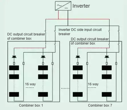
Affected by solar power curtailment, only 2 inverters in the whole station were in normal operation when the accident occurred, and the rest of the inverters were controlled by the dispatching automatic power generation control AGC platform to operate with limited power. The No. 1 inverter in Area 71 is in power-limited operation, and the input circuit breaker on the DC side of the inverter and the grid-connected circuit breaker on the AC side are all closed. The inverter is connected to 7 combiner boxes downward, the DC output circuit breaker switch of the combiner box is closed, and the inverter and the combiner box are connected to the system. Disconnect the box-type transformer, No. 1 inverter and the 7 combiner boxes in Area 71 from the system, and check the photovoltaic modules, combiner boxes, inverters, and box-type transformers in turn, and found that the remaining 6 combiner box power supplies The modules are damaged to varying degrees, mainly manifested in the leakage of the input capacitor bulge and the damage to the ceramic gas discharge tube of the data acquisition module. During the inspection, it was also found that the V-phase output filter capacitor on the AC side of the inverter was burned out, and the metal oxide arrester connected to the V-phase busbar of the low-voltage circuit breaker on the low-voltage side of the box-type transformer was burned out. At the same time, it was found that the DC fuse and anti-reverse diode of the string incoming line were not damaged, and the DC output circuit breaker was not tripped. Measure the incoming line string of No. 1 combiner box, and find that 4 branches are short-circuited to ground. The cable trench was dug on site and the cables were taken out. It was found that four photovoltaic cables were sintered together, and one of them was blown. Hot burn marks are found at the base of the corresponding incoming fuse. Check the PV incoming cables of other combiner boxes, and no abnormality is found.
3 Accident Analysis
3.1 The system operation mode after the two strings are short-circuited and grounded
(1) After the incoming cable of the PV string is short-circuited and grounded, a low-impedance point is formed at the short-circuit point, the currents of other strings converge to the short-circuit point, and the anti-reverse diode of the short-circuit string transitions from the forward conduction state to the reverse saturation state , forming a clamp, and the short-circuit point only bears the short-circuit current of the string itself. Since the short-circuit current is small, it will not cause a large arc fire. It is more common that the photovoltaic cables are heated and sintered together.
(2) If the anti-reverse diode is subjected to a large reverse voltage during the turn-off process, resulting in reverse breakdown of the anti-reverse diode, the short-circuit branch will form a large current loop. One combiner box has a total of 16 photovoltaic strings. At this time, the short-circuit point will bear the short-circuit current of the remaining 15 photovoltaic strings. The current value is much larger than the operating current of the branch fuse. The DC fuse of the short-circuit branch is blown and released. Line ground.
According to the above two short-circuit grounding operation modes, combined with the on-site accident situation, it is determined that the positive busbar of the DC output circuit breaker of the combiner box is the short-circuit grounding fault point.
3.2 Causes of short circuit formation
After a short circuit occurs at the upper positive busbar of the DC circuit breaker of the No. 1 combiner box, the loads carried by the remaining six combiner boxes will be merged into the short-circuit point through the DC busbar to form a short-circuit loop. The current flowing at the short-circuit point is close to 864A (the sum of the instantaneous output currents of the 6 combiner boxes), and the DC circuit breaker of the combiner box is a GM-250P type photovoltaic special circuit breaker with a rated current of In=250A and an instantaneous action value of 10In, that is, 2500A. Therefore, the DC circuit breaker of the combiner box is not tripped. The short-circuit point busbar passes a large current in a short period of time, and DC arcing occurs, causing the equipment to catch fire. The 16-channel photovoltaic strings carried by the short-circuit combiner box enter the short-circuit state at the same time, and the anti-reverse diode forms the clamping protection.